Making one ceiling light circuit into multiple light circuits with fibaro dimmer 2 switches

Hi

My question is about electrical wiring of the lights in my living room, specifically about how to correctly wire Fibaro 2 dimmer switches.

We are renovating our living room, therefore we have the opportunity to expand the number of ceiling lights available. However, we did not renovate het electrical wiring in the walls, so we have a limited amount of wall switches. So now, multiple lights are operated by one switch. Based on other forum posts, I have an idea of what I think is the right solution, but I would love to have some confirmation on this forum, since you probably have more expertise than I have.

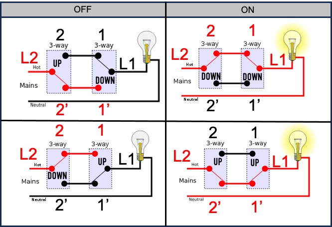
I made a drawing of what is (I think) our current situation:

So we have two two way switches controlling two lamps. Both lamps go on and of at the same time. The switches are the exact switches we have (Niko). I determined that the “L2” wire goes to the fuse box, since no matter how the switches are, this always has power. The “L” wire only has power when the lights are on, no matter how the switches are set. So… I think this is a correct plan.

To make it possible to control both lights separately, I think following lighting plan would work:

I would take out the switches and connect the wires “L2” and “2” and do the same to “L” and “1”. 1’ and 2’ I would just cover, they lose their function. Like that, the lights (and therefore the fibaro dimmers) are permanently powered. The holes in the wall would be covered by smart switches (I’m thinking Philips Hue tap dial - better suggestions welcome!!) that would then control the dimmers via the Homey Pro.

I also think this is the correct way to connect the Fibaro 2 dimmers. I have had great help from this post:

with special thanks to @robertklep and @Dijker from which I learned that attaching the blue wire is not necessary, but could help make the two bypasses redundant. I guess I just try and see if the lamps turn off completely or not to answer this bypass question?

So… My question is simple: are all my assumptions correct? Given that all the wiring is done correctly, is this a good/correct/safe way to make one ceiling light into two (and potentially even three or more if you add more dimmers)?

Thank you very much for your advice!
Roel

First of all, Congrats on making the very clear drawings,

Please read: WARNING: Electrical Safety is Paramount (Risks: Shock, Fire, Death by electrocution)

First What I see is they installed the wrong color wires, (if the Colors are correct in the drawing)
Only the incoming Live Wire (normally marked as L) in your first drawing on L2 dashed incoming from the Fuse box should be brown, all other Brown wires in the drawing should be Black. in that case is is a verry classic Multiway switching (in Dutch Hotelschakeling)

But seeing the colors (ignoring what you specify as Contacts) it is almost a Alternate Dutch alternatief
(But then the Contact don’t match your drawing)

Therefore it is not enough that you think the first is the current situation… Verify it, and work safe!

The good news, the Second drawing looks good, and would they have used Black wires where they should have been correct, you had to change them to brown… now these are already brown (in your drawing).

Hi Geurt

Thanks for the helpful advice. I tend to work cautiously, so even though I think I have it figured out, I would like your opinion on it. First of all, here is the drawing I made of the current situation with some pictures I took to double check.

I noticed that on the first sketch, I switched the brown and the black wire, so it is 1’ & 2’ that are connected through the brown wire and 1 & 2 through the black one, but fundamentally that doesn’t change the situation: indeed the wires do not have the right colours. “They”, being the previous owners, who renovated the electricity in this house used an electrical wire with 5 colours in it to connect the switches (see blue arrow): there is a grey wire that is not used, the blue wire and the grounding wire wire simply connected through and the brown and black wires were used to set up a system, which IS, I think, the classic multiway switching system. I grabbed the wikipedia picture you mentioned in your reply and measured every possible situation:

Lighting plan current situation test

… and this is what came out: every red wire in every situation was indeed ‘hot’ and every black wire in every situation was not. UP & DOWN indicate the position of the switch. It was the left switch that was in full control of whether 1 or 1’ was hot on the other switch, so I think this wiring is exactly what is happening in my house. I guess this also means that I can proceed with connecting the brown wires (which indeed makes the colour of the wiring correct) and then use black wiring after the fibaro switches.

Thanks again for the support!
Roel

Ah a VMVK Cable so that explains the Brown between the switches,

No Problem, that looks good and you now can use the Brown for the Line (L)

I don’t see any other issues with your drawing,
You can place an wall outlet where the two switches where and place the Remote above.

1 Like