Makes life easyer
3.depends on how things are wired now…
Your drowning is off anyway. Switches are between s1 or s2 & sx. If you wire it like this you’ll possible blow the module.
A 4 way hotel system is quite complex and a heavy wiring. Not impossible, but presumably a lot of work. 4 push switches are easier since then it’s almost as per your drowning. 1 line from s1 feeding all 4 switches and returning to sx.
Another possebilty is to use z-wave wall switches, those only require a feeding and no further wiring to the dimmer 2.
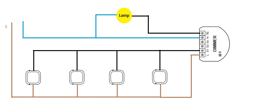
Thx for the info! Wiring diagram no. 5 needs only the S1 and Sx connected? Sorry, not an electricien here :). Can you maybe tell me what wires I need for diagram no. 5 and which colors they have?
Does this mean I have to install 2 wires to my pulse switches? One goes to S1 and other one comes from Sx to the switch?
Thx for the info! Wiring diagram no. 5 needs only the S1 and Sx connected? Sorry, not an electricien here :). Can you maybe tell me what wires I need for diagram no. 5 and which colors they have?
No, you’ll have to do the others as per your drawing;
Brown → L
Blue → N
Black => symbol thingy
s1 to switch → whatever you want
switch to sx → whatever you want. I just used black and used some tape to mark them as “other”
Does this mean I have to install 2 wires to my pulse switches? One goes to S1 and other one comes from Sx to the switch?
Will it also work without Sx and using L (brown) to feed the switches? If not, what goes wrong then? I hear from others that the Sx isn’t required and my drawing would work also
Too be honest i’m not sure. Spend some time to confirm what you/they say but it might work if Sx is the same as L (measure between Sx & N). Internet seems to say its the same as input (230v) but i don’t have a unit close so i can’t check personally. If its indeed the same as L then in theorie you could feed your switch with L instead of sx and go to S1/S2, if there is no “smart” thing going on inbetween Sx/S1,2.
However, not a single fibaro wiring diagram supposes that solution. It might just work fine but i’m not sure what it will do on “millage” and besides that, i mostly like to follow the official diagrams when i’m wiring the place where i also sleep.
I am curious though, so let me know if you find anything on that. Mayby someone else can chip in on this.
@roel_hendr Confirm, I have several dimmers mounted in the ceiling above the lamp and I powered the dimmers on L and N. I used the existing black wire from the existing switch and connected that to S1 (Sx is unused in this case) so, for me, this is the easiest way to install a dimmer in an existing situation, it can also be used in case of “Hotel schakeling” as you mentioned.
@JPe4619 That sounds good! Do you have normal switches in your setup or pulse switches? If these are normal switches, can you use these to dim the light(s) by holding the button?
It is not very wise to use only the S1 or S2 without it being on a separate wire connected to Sx. Live (brown, not from Sx) in S1 or S2 could cause serious hazards. The module is rated for 10A and a typical circuitbraker is 16A . So if the combined load of the group on this same circuitbraker is more then 10A the module will fry or catch fire. It’ll work nevertheless if you are sure there is never going to be more then 6A continues load or 10A peak load on the group/circuit. Further more i think the S1 and S2 have limited load input as this part of the internal circuit only uses 300mA for switch detection.
In case of a shortcut in the group there will be momentarily a peak load of several 100A depending on what circuitbraker you have in use. As pro electro installer i totally do NOT recomment to do this this way. For this to work you need extra fibaro modules to use the switch part and the last one in line connect the bulb itself. Or get the first switch in the line, where the brown live is connected and take brown out and replace that with a black/white one running all the way to the bulb and use a single fibaro there. You can combine all with association setting in the fibaro devices themselves. If you need dimming then use all dimmers and momentary switches, just on/off you can use the single relais.
You mention 2 solutions. Can you maybe add 2 drawings for them? It makes it more clear for me as a non-electric expert I’m interested in the one where you only have one Fibaro dimmer between first switch and lamp.
I rather not wanna buy 4 Fibaro modules for this scenario, as you know they are quite expensive
This is false, the dimmer 2’s output is only 300 watt max, so by far not the 10A more like 1,5A
The inputs will never see more then a few mA as there is no load with them in series, only in parallel, the output is completely separate from the inputs.
Wasn’t talking about the outputs. Fibaro says so themselves, so who are we to know it better? Also they will confirm that it is not correct to only connect switch wire to S1 or 2 and it will invalidate any warranty.
And yes if you use the input without it being separate looped over Sx then it does carry the load of the whole group after this point, taking the shortest way over the wiring.
Then you probably never seen the inside of an dimmer 2, and have not seen the direct connection that goes from L to Sx, so the only difference of safety you imply to is the burn rate of the PCB’s tracks, as there isn’t even a safety resistor (0 ohm) in there.
Fibaro has to say that to cover their own asses, so us people can’t blame them/take them to court.
So you can tell me who is correct here
Just installed it like this. Kept the existing normal switches, just placed the dimmer between the lamp and the ‘last’ switch. Then changed configuration in dimmer that its connected with normal switch (no pulse) and it works like a charm. Indeed not possible to dim with the switches itself.
Well if that is so, then it wouldn’t matter as long it is on the same circuitbreaker. It be just fine to put the module between the black bulb switch wire.
What if the sx and switch contacts are fused separately ? If this is so you can definitely cause serious damage or fire.
There mustbe is a good reason why fibaro has a a sx, s1 and s2.
There’s a lot of interesting info in this thread on the Fibaro forum. Connecting as suggested isn’t a problem (electrically speaking), but it may cause false or missed triggering.