as @Undertaker already posted I’m going to mod the bridge, as i would like to use it as BLE Beacon recon. So BLE cold be little be better in coverage and as the app not jet available in the beta, I was thinking on going for the mod first:
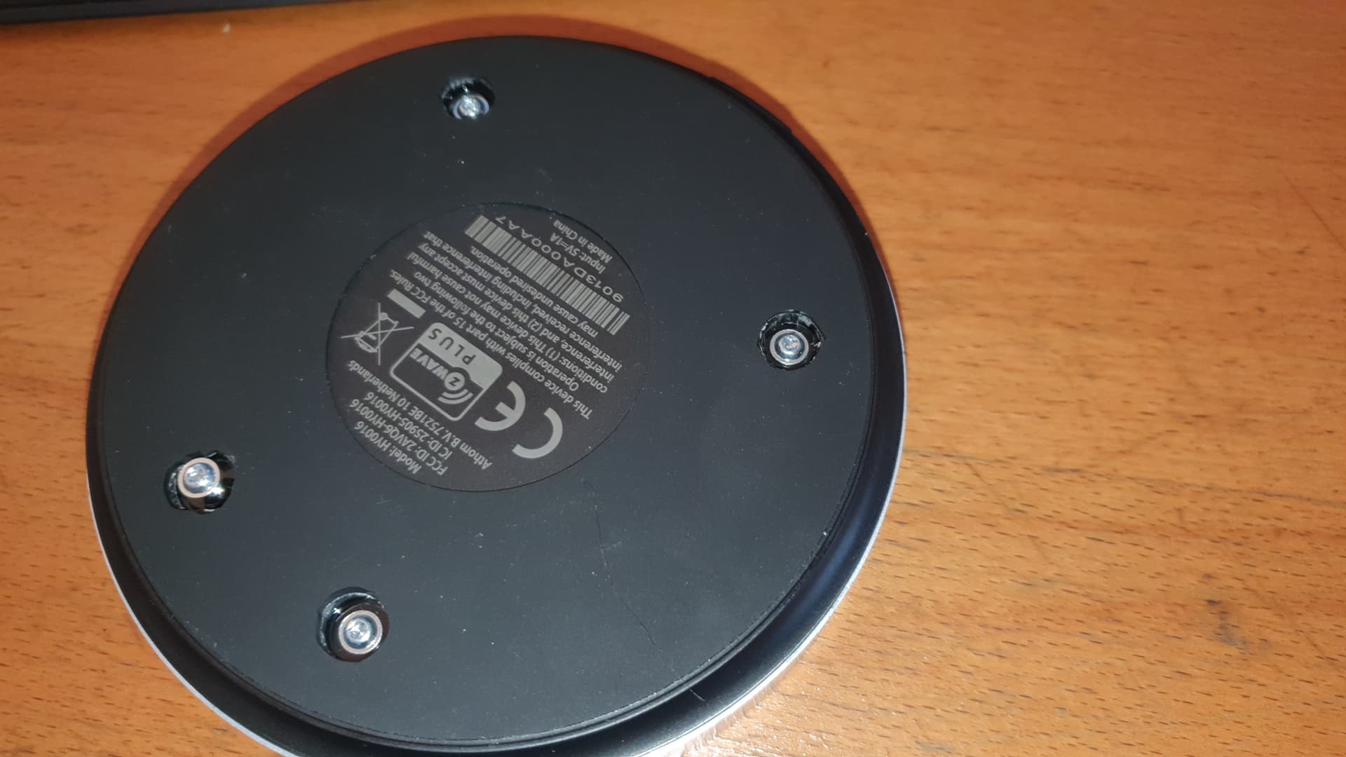
locating the screws
The new bridge will be an Eldorado for antenna mods. Why ?
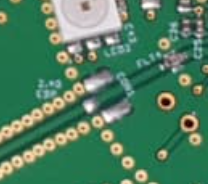
There are so-called IPEX sockets on the circuit board of the bridge. They seem to be available for every radio standard. When a plug is connected to this socket, it automatically disconnects the internal antenna and routes the signal to an external antenna socket. Much stronger antennas can then be connected to these sockets. The puck also seems to have enough space to install these antenna sockets in the pane. The whole thing can be done without soldering.
I am looking forward to the first reports as to how the range is in the original state. Otherwise I’ll probably slaughter a bridge and try the whole thing.
Anyone “modified” their bridge yet? Soldered on some antenna’s?
Very curious if my newly bought Bridge (intentionally just to play around with; curious nature here) could reach my mailbox from the basement.
That basement is a little nearer to the mailbox, but the Bridge doesn’t reach it unfortunately. Still got a nice Z-wave antenna and amplifier lying around here…
Could integrate a sensor into my Homey Pro by http request if this works….
Yes, I had converted a bridge to an antenna mod with Zigbee and Zwave at the time. The range was much better.
But since I didn’t like the concept of the bridge, I sold it again. I have not heard any complaints from the buyer that he has problems with the modification.
But you had the connectors already in place, hadn’t you?
Or soldered it on too?
I only use Shelly actuators and Aqara sensors in my basement, so I don’t even have to connect the Shelly’s by http. The bridge and the Pro can manage them both, since its’s done by wifi/http, which is one network for both Pro and Bridge.
The Bridge might even be a better solution than I thought beforehand!
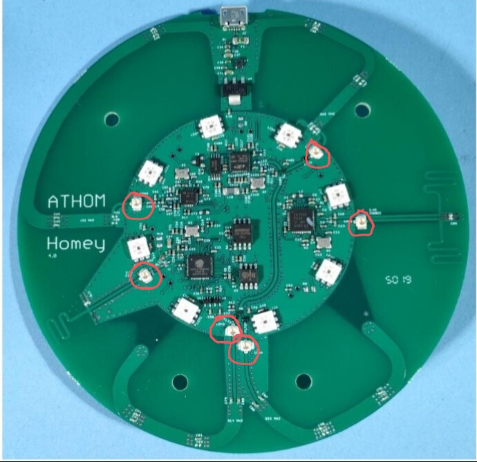
I had to solder in the pigtails. To do this, I cut the original antenna lines as I did with the Pro and soldered the centre conductor to the antenna track. The antenna shield was connected to a ground point on the circuit board.
Unfortunately, I didn’t take any photos at the time.
The bridge intended for the market does not have IPEX sockets. Open your bridge and check.
These sockets were originally only present in Athom’s test devices to read out various information. You have no other option than to manually disconnect the built-in antennas.
I know, some soldering is no problem at all.
But you wrote that the original built-in antenna’s were automatically disconnected as soon as you connect other antenna’s to the sockets…
Why still the need to cut the original antenna tracks then?
If i remember correctly Athom mentioned on slack the connectors are only soldered on the examples sent to testing labs like in the pictures on FccID.
So you have to solder yourself
Yes, like @Undertaker said…
Soldering is no problem.
But why cut the original tracks when the original antenna’s are disconnected automatically when you connect an external antenna to the connector?