need some help.
How should I connect the Fibaro smart implant to my Faac gate controller unit?
I am not an electrician and don’t want to do any mistakes.
See attached image (sorry about the Swedish).
Is it correct that the outputs on the smart implant are not used? They could potentially be used for knowing whether the magnetic lock (gate closed) is actived or not?
So from the implant (left side):
To be able to answer this question, someone must be able to understand the operating instructions. I can’t.
What is the name (model no.) of the gate controller/opener?
Power supply for Smart Implant (24 V DC):
FAAC Board: OUT1 + → Smart Implant: P (red wire)
FAAC Board: OUT1 - → Smart Implant: GND (blue wire)
FAAC Board: OUT1 must be set as ALWAYS ACTIVE (default)
Smart Implant OUT1: Start/Stop → FAAC Board: IN / IN1
Smart Implant OUT1: GND → FAAC Board: IN / GND
Nice to have
Please have a look at this thread. This thread explains how to configure the Smart Implant and how to connect e.g. proximity switches or reed contacts.
Nope, that did not work. The Faac Out1 was busy so I used out2 but I assume same logic applies. Couldn’t add the z-wave even though homey was just 1cm away. What also happened was the regular gate controller stopped working as well.
Didn’t dare to try using out1 also for the Smart implant but maybe I should have?
You mean pairing the Smart Implant? Is it powered correctly? And, sometimes you have to repeat the pair process many times before it finally gets paired.
First of all: Before you connect and include the Smart Implant to the gate controller, I strongly recommend that you make the necessary settings (e.g. separate the inputs from the outputs) and tests with proximity switches or reed contacts at your desk and try them out if it works as it should!
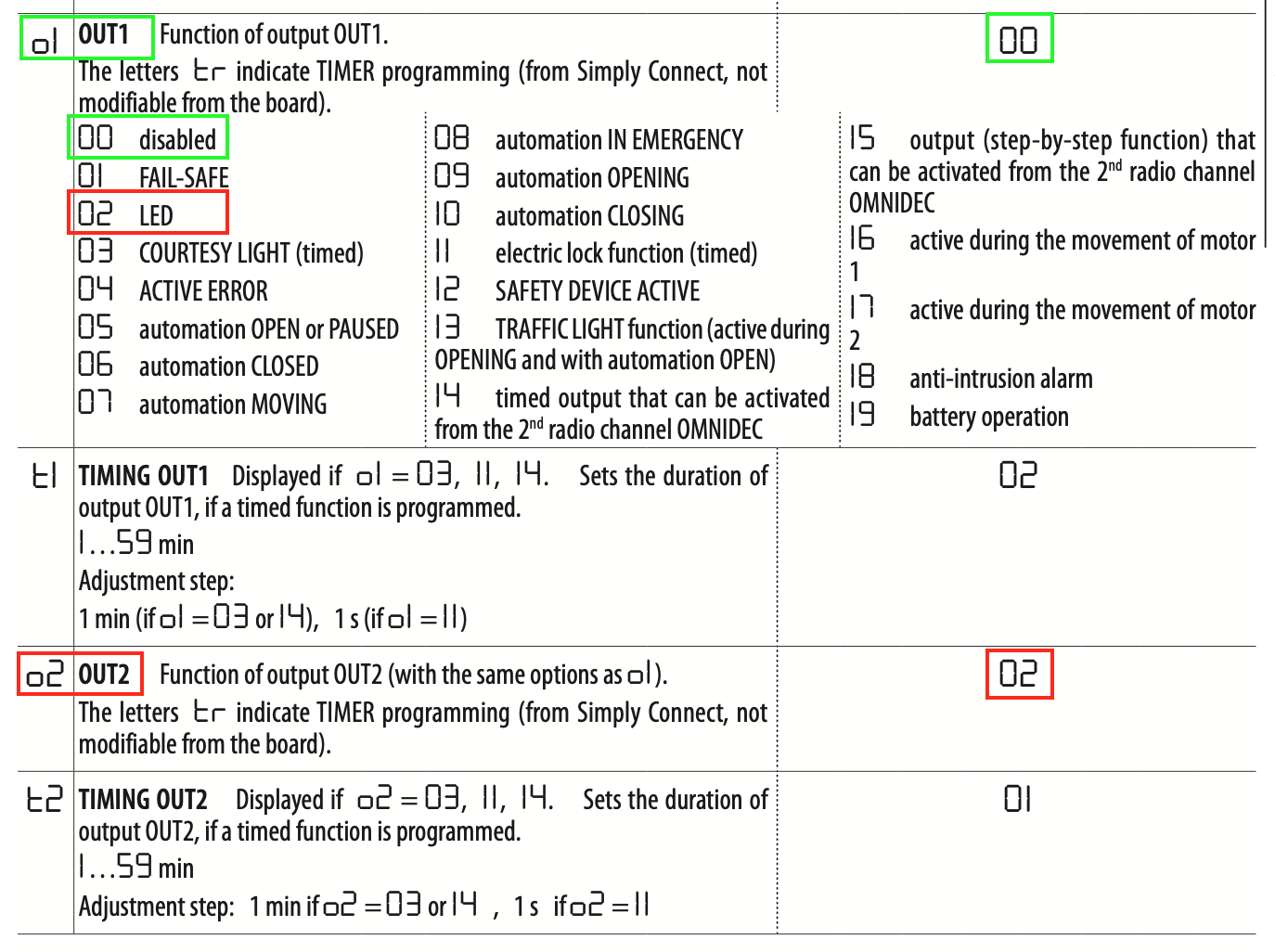
OUT2
I guess if you want to use OUT2 in the same way as OUT1 you have to configure OUT2, because OUT2 is different configured.
I guess you must set OUT2 to “00 disabled” (with no TIMER), but I don’t know if it is correct, sorry.
However, you can use a multimeter to check whether a voltage of 24 V DC is permanently present after the change to “00 disabled”.