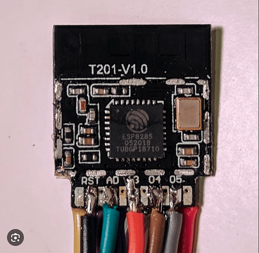
I am connected to my wifi using android BlitzHome and I have IP and mac address. Is there a way I can communicate with the device. I need to know the hardware properties and hopefully reflash it with Tasmota. Can you help. ( I have all the details regarding the flashing using toya-convert)
You’ll have to open up the device to check the chip brand/type
Thanks for the tip. I did but unfortionaly the chip was covered with wifi shield. I managed to get the part number of the module and the chip is ESP8285. The module is T201-V1. 0
I have been looking for pinout to access the TX and RX so I can Reflash the plug with Tasmota; I could not find any clear pinout for the module.The silk screen on the module was:
V3.3
Ground
I04
RX
013
TX
I02
RST
The writing is so bad that I am not sure of the correct sequence. As for the GPIO 0 ( needed for reflash) was actually printed on the board clearly. My problem is RX and TX. If you can help me find CLEAR pinout of the module ( not the chip) it will be great
Followup:
The two figures for the fron and the back of the module. all the screen labels are exaxltly the same as mine. The problem: There are access to SIX soldering point where I can solder wires BUT none of them show the RX and TX They are soldered to the back of the module. I will try to send you a pysical picture of what I am describing. Hold on
It sounds like you have to remove the module so you can access the solder points on the back. My guess would be that the RX and TX pins aren’t going anywhere on the main PCB where this module slots in (at least, this looks like a slot-through module) because they aren’t used for anything other than initial programming.
I’m not sure what you’re expecting here: you know where to find the RX and TX pins ![]()
Before I solder the RX and TX I want to make sure that these are the correct one’s. At the moment I cannot.May be by looking at the schematic I will be able to find a connection to test it. But you are right, the two are looking at me…just kidding
When I posted this issue I was hoping that some here did the reflashing of Tuya device. As I was waiting for response I gathered enough data to help us out. The problem was the way the manufacturer designed the board. He/she had no entention of making RX/TX easily available. In the case of the T102 module (small sqaure board mounted VERICALLY); the module has 11 pins please see the figure above in the post. The designer decided to expose 6 and embed 5 to the main board. Of course the exposed 5 did not include RX/TX. That is why it was exremely difficult for me to access these points.
Since I was not lucky to find someone here that did it ( The plug is very popular), I decided to abonedone the hardwiring and try software solution. Luckly I found the solution and it all evolve around “Tuya-convert”. I did it and I now have latest Tasmota running as a power monitor.
If anyone interested, I am ready to provide all the details needed.


